

The Cloud Absorption Radiometer measures scattered light in 14 spectral bands.
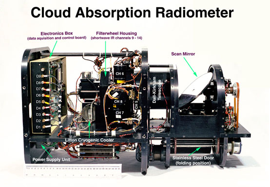
The Cloud Absorption Radiometer (CAR), considered the most frequently used airborne instrument built in-house at NASA Goddard Space Flight Center, is capable of measuring scattered light by clouds in fourteen spectral bands. To load an expanded view of the CAR instrument, with many of the mechanical, optical, and electronic components identified, click on the thumbnail image to the right.
The scan mirror, rotating at 100 rpm, directs the light into a Dall-Kirkham telescope where the beam is split into nine paths. Eight light beams pass through beam splitters, dichroics, and lenses to individual detectors (0.34 - 1.27 µm), and finally are registered by eight data channels. They are sampled simultaneously and continuously. The ninth beam passes through a spinning filter wheel to a Stirling cycle cooler. Signals registered by the ninth data channel are selected from among six spectral bands (1.55 - 2.30 µm). The filter wheel can either cycle through all six spectral bands at a prescribed interval (usually changing filters every fifth scan line), or lock onto any one of the six spectral bands and sample it continuously.
 |
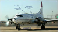
| The CAR instrument is housed in the nose of the CV-580 aircraft. In this photo, CAR's stainless steel sliding door is in the closed position, protecting the scan mirror and optics assembly from dust and other foreign objects during takeoff and landing. + Larger image (opens in a new window) |
The electronic functions of the cloud absorption radiometer are mainly divided into three physical sections: scanner, control, and data acquisition. The analog signal is digitized internally to 16 bits at a rate of 1.2 kHz and then transmitted serially at a baud rate of 460.8 kbits per second to an external flight computer for display and storage. Also built into the data acquisition system are two reference voltages. The front-end 7.5 V reference voltage that provides temperature stable reference to translate the input voltage to be compatible with analog digital converter and a 2.5 V reference voltage for providing an external reference to the analog digital converter. The conversion from voltage to radiance is accomplished through a laboratory pre-and-post-flight calibration procedure.
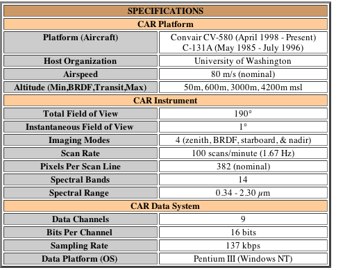
The CAR scan mirror scans 360° in a plane perpendicular to the direction of flight and the data are collected through a 190° field of view. In the normal mode of operation onboard the CV-580 aircraft, the CAR views 190° of earth-atmosphere scene around the starboard horizon. This configuration permits observations of both local zenith and nadir with as much as a 5° aircraft roll. In addition to the starboard viewing mode, the CAR instrument can now be rotated in-flight into three other viewing positions: downward-looking imaging mode, upward-looking imaging mode and a dedicated BRDF viewing mode.
The instrument incorporates several novel features. Since it is sometime flown through clouds, there is the possibility that moisture may be deposited on optical surfaces, especially the scan mirror, producing large errors. The instrument is mounted outside the airplane and cannot be observed in flight. In order to check for water on the mirror, a unique detection system was devised. A thin beam of light is shone on the edge of the mirror, and the reflected beam is monitored by a photodiode. If any condensation appears on the mirror the reflected light scatters, reducing the photodiode's output and flagging data likely to be in error. Another novel feature maintains low offset (ensuring that zero volts at the output always correspond to a zero-radiance input) by using the scan mirror as a type of radiation chopper. It works by forcing the electrical output to zero during each backscan while the detectors are all completely darkened by means of a scanner-synchronized moveable shutter. Long time constant coupling in the amplifier then ensures that data measured during the active part of the scan remains accurately related to this zero reference level.
 |
| Table 1: Summaries of the characteristics of the CAR sensor, platform and scanning system. |
 |
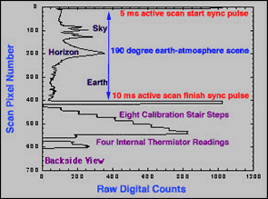
| Sample digital output of a complete scan cycle from one of the CAR spectral channels. |
At the beginning of each mirror scan cycle, the CAR data acquisition system first records a ten byte header. It contains information such as flight number, current date, roll angle and scan line counter, etc. Following the header is the data stream from eight data channels. Figure 3 shows a sample digital output of one complete scan from one of the CAR channels. Two sync pulses denote the start and end of an active scan segment. These pulses are distinguished by their differing time durations. Assuming zero aircraft roll and pitch angle, the CAR scan mirror should be looking at 5° before zenith direction at the first pulse and 5° past nadir at the second pulse. Also multiplexed into each channel on each scan cycle are the set of reference voltage as well as measurements from the four internal thermistors. The reference voltages range from 0.00 to 8.00 V in steps of 1.00 V and give the appearance of a staircase. This voltage staircase permits the conversion of digital counts to voltage, while the conversion from voltage to radiance is accomplished through a laboratory pre-and-post-flight calibration procedure.
The CAR has undergone several modifications and improvements over the years, including:
Further information can be found in King, M. D., M. G. Strange, P. Leone and L. R. Blaine, 1986: Multiwavelength scanning radiometer for airborne measurements of scattered radiation within clouds. Journal of Atmospheric Oceanic Technology, 3, 513-522.