

CAR Instrument Cutaway Detail
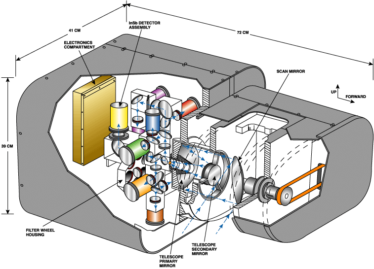
Shown to the right is a cutaway illustration of the Cloud Absorption Radiometer (CAR). The instrument housing is approximately 72 cm long, 41 cm wide, and 39 cm deep; and weighs 42 kg. The CAR is capable of measuring scattered light in fourteen spectral bands between 0.34 and 2.30 µm. The scan mirror rotates at 100 rpm and directs the light into a Dall-Kirkham telescope, where it is focussed into a narrow beam and passed onto specially designed dichroic beam splitters, mirrors, lenses, and filters to individual detectors (Image modified by Gatebe and Gammage from King et al., 1986).
 |
Schematic Illustration of the CAR Instrument. + Larger image (opens in a new window) |
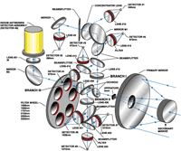
Depicted to the right is a schematic illustration of the Cloud Absorption Radiometer optical system. The radiation having left the secondary mirror first passes through the defining field-stop and then through a pair of specially designed dichroic beam splitters. The radiation reflected by the first dichroic (D1) enters branch I and is of wavelength range of 0.34 to 0.87 µm. The radiation transmitted by D1 and reflected by D2 enters branch II where it is separated into three channels in a similar manner containing filters in the 1.03 to 1.27 µm interval. The radiation transmitted by D2 enters branch III, where it is further defined spectrally by a filter wheel containing six narrowband interference filters in the wavelength range 1.55-2.30 µm. (Image modified by Gatebe, Nguyen, Bly and Gammage from King et al., 1986).
 |
Illustration fo the CAR Data Cycle. + Larger image (opens in a new window) |
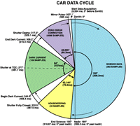
The CAR data cycle, depicted in the graphic to the right, is dictated by a mirror scan cycle that takes 600 ms for a complete rotation. At the start of the data cycle the CAR data acquisition system first records aircraft navigation data followed by serial data from the instrument. The instrument data comprises four types:
At the beginning of each mirror scan cycle, the CAR data acquisition system first records a forty-four byte header. It contains information such as flight number, current time and date, roll and pitch angles, heading, latitude and longitude, etc. Following the header is the science data stream, 7740 bytes from ten data channels. This data stream is for the signal collected through the 190° opening. We note here that the tenth channel is used as a spare channel and is not connected to a detector. The science data stream is followed by 40 bytes of housekeeping data containing information on temperature of detectors, mirror heater status, door status, and position of the filter wheel, etc. Following the house keeping stream are 2560 bytes of dark current signals from the ten channels during each backscan when the detectors are all completely darkened by means of a scanner-synchronized moveable shutter. The last interval in the cycle is used for internal calibration of the data input ports to give a zero volt reference. Assuming zero aircraft roll and pitch angle, the CAR scan mirror should be looking at 5° before zenith direction at the first pulse and 5°past nadir at the second pulse.
After a flight mission the data are transferred to a ground computer for post processing. This involves first separating the various data types, header (navigation), the science, housekeeping, and dark current. Secondly, the science data is corrected for aircraft roll so that the first pixel in each scan corresponds to 5° before zenith and the last one 5° after nadir. Also, in each scan an average of dark current signal is subtracted from each value of the science data signal of the following scan. Thirdly, the resulting product is converted to radiance units using the calibration constants computed during the pre-and post-flight calibrations. Finally, data are geographically and time referenced before they are archived for use by the scientific community. (Image created by Jones, Nguyen, Gammage and Gatebe.)
 |
Block Diagram of the CAR Instrument Electronics. + Larger image (opens in a new window) |
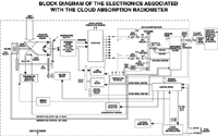
Shown to the right is a block diagram of the electronics associated with the Cloud Absorption Radiometer. The electronic functions of the CAR are mainly divided into three physical sections. These sections are:
Both aircraft supply 115 V ac, 60 Hz, and 28 V dc power. The analog signal is digitized internally to 16 bits and then transmitted serially to an external flight computer for display and storage. (Image modified by Gatebe, Jones, Nguyen and Gammage from King et al., 1986).